I have finally finished this amplifier. I am pretty happy with it. It sounds great!
To get this amplifier to where it is now I had to completely replace everything except the pots, power transformer, and tube sockets. Although that sounds like a lot it was not to bad and it allowed me to be certain everything was wired correctly and all resistor values were correct.


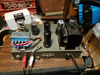
 As you can see I added the 12SL7 where the old capacitor can used to be. The 12SL7 works great for a microphone input, but it gets by passed when used for input from audio source such as my turntable. Also, you can see I have replaced the output transformer with a new one from Edcor USA.

To get this amplifier to where it is now I had to completely replace everything except the pots, power transformer, and tube sockets. Although that sounds like a lot it was not to bad and it allowed me to be certain everything was wired correctly and all resistor values were correct.


What is your power transformer? I have the A7. The power transformer went up in smoke. So I am looking for a replacement. Not sure were to start. hoping you can give me a hint on what a replacement might be. The one I have is a 54-25.
ReplyDeleteMy power transformer is labeled 54-3. It has 400V from the full wave rectifier. I would look for a transformer with a 450 CT and 12v and 5v filament.
ReplyDelete